CTC
312 – Microstation V8i
Student
Examples of Rendered Drawings (Spring 14)
Carles
Lojano (Civil Engr. Technology)
For the MicroStation final project I decided to do a 3D drawing of the “One World Trade Tower” at the World Trade Center in New York City. I chose to do this project because I moved to New York just a few months after the 911 attacks and I never saw the original twin towers. Also I live close to New York City therefore; I had the opportunity to see the construction of the new tower (from the concrete foundation to the steel erection to the glass surface.) Also, I chose to design this tower because it is related to both of my fields of interest: Civil Engineering and Architecture. The way that I designed this tower is by drawing a 200 ft X 200 ft square base and extruding it 1,368 ft just like the original height of the one world trade tower. The most difficult part of this project was to make the outer walls triangles and upside-down triangles. The way that I designed was by drawing a rhombus from the top square of the tower and extruding it down to the base. After these two solids were completed I deleted the extras between the square base and rhombus top in order to get a triangle wall followed by an upside-down triangle wall all around the tower. Also, the triangles meet at the top of the tower at an angle just like the original tower. An important part in this project was to apply the right materials to the solids. I applied glass to the triangle walls so that anything on the ground would reflect on the glass. In order to have a reflection and a shadow of solids I also applied solar and ambient light. The solar and ambient hour is 11:30 am, sunny and clear sky. Also I applied roads, trees and grass around to make it look like the world trade center. Another important and symbolic part was to add an antenna to the top of the tower in order to complete the original height of the tower (1776 ft). The antenna was created using solid circles, solid cones and galvanized steel material to make it look more realistic. I am glad that I had the opportunity to use my MicroStation skills on a 3D drawing especially on something so meaningful to this country like the World Trade Center.
Brad
Allen (Civil Engr. Technology)
For my Micro Station Final, I designed a steel storage shed. I left the building like this to portray to others what a steel shed would look like if left as a steel frame. I also designed base plates for the columns. I didn’t want to follow a standard convention however, and drew the trusses as a wood frame design. I added two lights to the drawing and made the drawing seem as if it was still under construction and at night. I added two sheets of metal to one side of the building to make it appear as if it was still under construction, while allowing interior details to be seen. The columns are standard sizes taken out of the steel manual and the base plates were designed to standard specifications. There were two problems I had when drawing this. The first problem I ran into was designing the trusses. Since these are all solid objects they did not want to “snap” together and needed to be extruded as individual pieces. This then became a bigger problem when trying to set them into place on the interior beams. The other problem I ran into was figuring out the lighting. I wanted this to be set at night and had multiple issues with making this appear the way it does. There are several light settings which should not be touched and others which need to be magnified to a great extent. This meant that I had to try changing settings one at a time and re rendering to get the desired effect I wanted. In order to make this drawing look realistic, materials were assigned to specific solids in this drawing. Each type of material was given a different layer. There were 6 different layers in this drawing. There was a specific layer for each of the following: grass, trees, steel frame, light posts, concrete slab, and steel siding. I chose this drawing because I thought the lights would look great against a dark background would look nice against a steel frame. I also wanted to choose something related to Civil Engineering Technology, which made this the perfect fit.
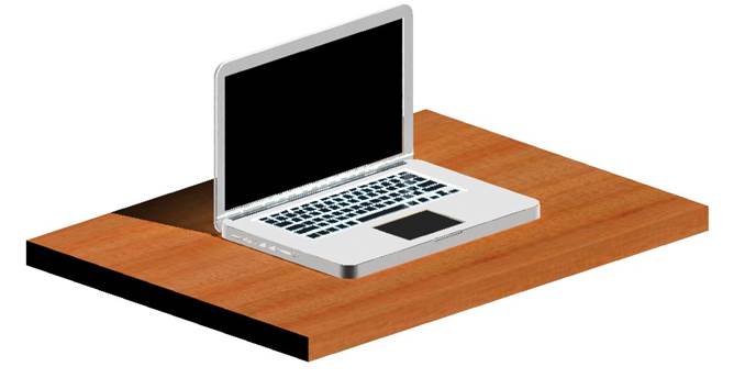
Pre-rendered Model:
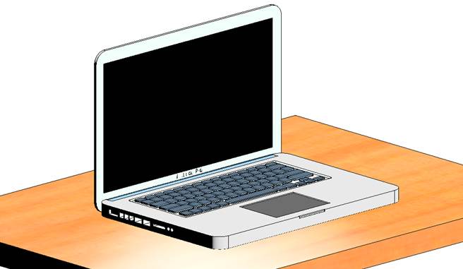
Pre-rendered Keyboard
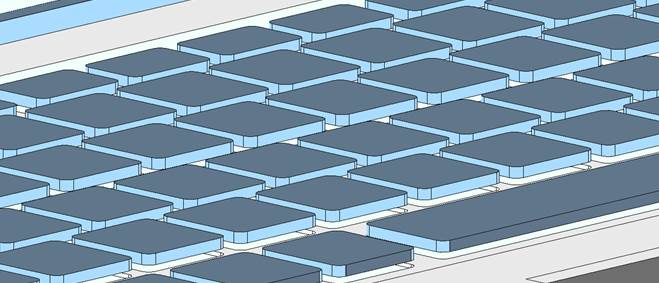
Final Render
Sean
Sweeney (Civil Engr. Technology)
An Apple MacBook Pro 2011 model was measured and recreated in Microstation using three levels. The three levels used are labeled ‘MacBook body’, ‘Keys’ and ‘Lights’. The body of the model was created using a slab solid measuring 14.5” x 10” x 0.75”. These dimensions were measured using an engineer’s scale and referenced to the dimensions released by Apple Computers. The screen was also created using a slab solid measuring 14.5” x 9.5” x 0.175”. Since the MacBook Pro’s body is not comprised of 90° angles at the corners but rather rounded edges, the ‘fillet edges’ tool was used to round all corners with radius of 0.75” The most tedious part of this design was the keyboard design. The body of the MacBook Pro has a cross sectional area in which the keys sit in. This area is only a fraction of an inch larger than the keys themselves. This area allows room for the backlit LED’s to shine through the base of the keys. In order to create this cross sectional area, each key was measured and created using the ‘solids slab’ tool. Again, all corners of these keys were rounded using the ‘fillet edges’ tool. Once these keys were created, they were placed in relation to one another as they are on the keyboard. These keys were then copied and scaled up in all directions by a very small fraction of an inch. Once this was done, the ‘subtract solids’ tool was used to create the area mentioned above. The remaining copy of the keys was then placed in the cross-sectional area in which they belong. In each of the 78 cross-sectional areas, a spot light was placed to best resemble a backlit keyboard.
All other openings and cutouts from the MacBook Pro body were created using ‘slab solids’ followed by placing these solids where open areas are present. They were then subtracted using the ‘subtract solids’ tool. This method was used to create the keyboard, track pad, charging port, Ethernet cable port, both USB ports, headphone jack, SD card port, body to screen hinge, and the CD ROM.
Jack
Caraher (Civil Engr. Technology)
For my drawing I created a pergola. I built one on the deck at my house and one out back in the yard similar to this one. They are great for landscaping purposes and look great once completed. For this drawing it was difficult at first trying to create the first post and beam. It took time to complete, but once I was able to complete the first post and beam, the rest could be copied. Another very difficult part was the first top beam to groove in correctly with the beam under it, but like before once completed it was just a simple copy. The way the pergola works is the top beam should just be able sit in place tightly over the beam it is placed on. I also added trees to this drawing. I created a cylinder then added a cone to the top of the cylinder. The material for the tree can be found under the landscape palette. Unfortunately there is no tree material, so I used rough wild grass which looked the best on the trees.
Jeremy
Torres (Civil Engr. Technology)
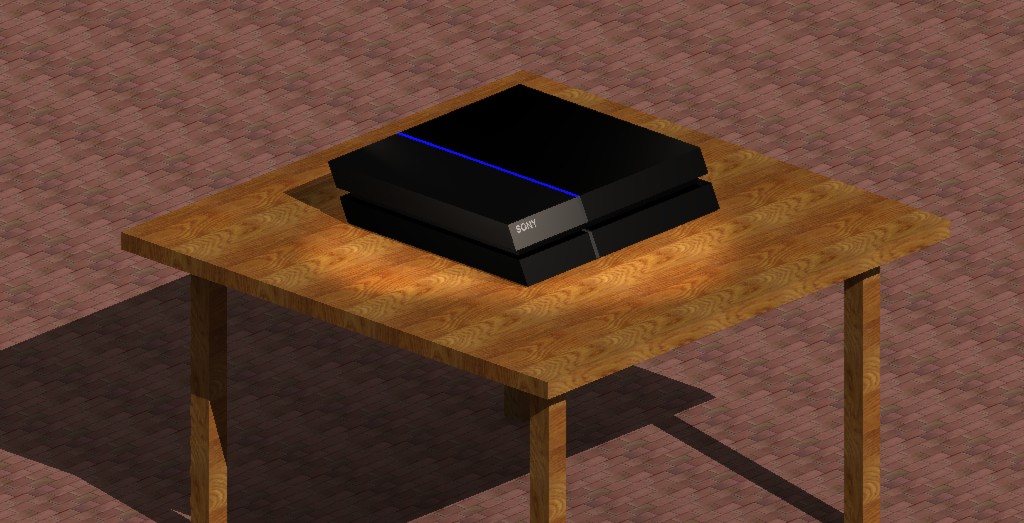
For this final project I created a 3-D model of the Sony PlayStation 4. It is a video game console released in November of 2013. The model shows the physical console sitting on a wooden table with lights projected on to all four sides of the object. The front of the console is slanted on an angle, with one portion made of a reflective plastic. The rest of the console is covered in a more rough plastic and has a blue light bar on the top that changes different colors depending on what power state the system is in. There is also a disc drive and two USB ports on the front of the console, but I had some trouble getting those to appear in the final image. There are also many symbols on the top, front, and left side of the console, but I could not figure out how to place those images on the correct face of the object. This includes the PlayStation symbol, the power button symbol, and the “PS4” symbol. Also, symbols denoting that the system has HDMI, Blu-Ray, and other capabilities could not be presented in the model. It was also a challenge to have the “SONY” label to appear correctly because the face that it is placed on is at a 65° angle.
Another problem encountered was getting the material on the table and floor to appear correctly. The original model had to be scaled down to 1/16th of its size so that the wood of the table and the bricks in the floor could be noticeable.
Anthony
Seale (Civil Engr. Technology)
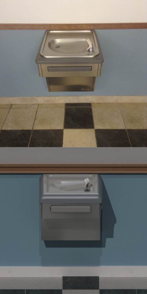
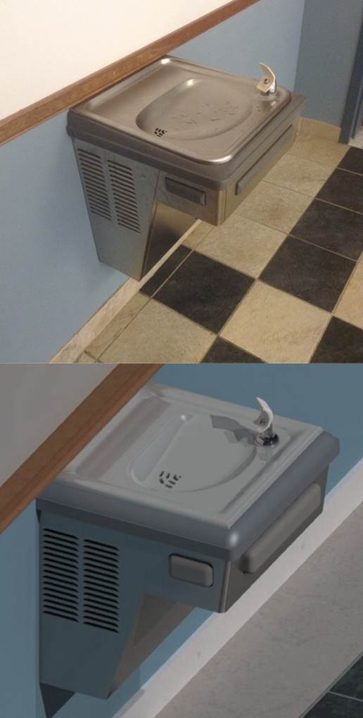
Actual
Photos-Top; Rendered Model-Bottom
Choosing my drawing took a while. It came to me when I was getting a drink and I looked down and decided I was going to draw a water fountain. I thought "how hard could it be, it’s just a box", but some parts proved challenging. The total drawing has 11 levels. They include the sink, faucet, faucet splash guard, plastic molding, metal box, push bars, the wall, wall molding, the floor, the floor molding, and the floor tiles. I decided to start by drawing the sink. I drew rectangles and then meshed each area and then connected them. Once it became a whole, I extruded it down far enough so that I could put a drainage basin into it. Then I applied a fillet to all the edges to make it smooth and as close as I could get it to the real sink.
Making the drainage basin was actually easier than I thought it would be. I drew a solid rectangle (which I should have done for the sink, but I wasn't going to delete what I had already spent 2 hours making). The solid had varying fillets on the corners that closely matched the shape of the real basin. The solid was then placed inside the sink and the “subtract solid tool” was used (which was arguably the most used tool for this project). The edges had a fillet again to smooth the connection.
The faucet was a little challenging. A dome was placed for the base and then a cone-like solid was placed on top of that. Creating the splash guard was the hard part. I placed two 2d ovals, one small and one a little bigger, so they intersected and deleted the unnecessary parts. A mesh was created for the 2d shape and I honestly don't remember how I got it to become a solid (I got lucky). I applied a fillet to the back side so that it would have a curve to it, but it didn't want to work with me. Once I got it to look as close as I could, I rotated it 45 degrees and copied it. The copy was used to delete part of the cone faucet. The original guard was then moved into position. The water outlet at the tip of the faucet was fairly easy. A cone was made and then a section cut from it to make a circular trapezoid shape. A sphere was subtracted out of it along with two perpendicular skinny rectangles. The outlet was then rotated 45 degrees in two of the views and moved into position.
The plastic molding was also easy to make. Two solid boxes were created, one big and another a little smaller placed on top of the big box. Another box subtracted the inside of both boxes, so the molding could fit around the sink. A fillet was applied to the top edges of the top, smaller box. The metal box for the water fountain was made using two different sized solid boxes. The front faces were tapered a bit on both these boxes. Push bars were made by placing a solid box and applying a fillet to all the front edges. Another one was made that was a hair bigger, which was used to subtract the volume out of the metal box. The push bar was moved into position and the technique was repeated for the other two sides only with smaller bars. The last part of constructing the fountain was to subtract volumes out of the metal box and sink for the vents and drain hole respectively. Solids were made as close as possible and subtracted the drain holes all the way through the sink and the vents partially into the box but not all the way through.
Materials were not easy to get to look close to the real thing, but after much tinkering, I figured out how to adjust them. Only one directional light was used to create shadows and a wall, wall wood molding, floor marble molding, and floor tiles were created for added decoration. In the end, I lost count of how long it took to make this, but it was well over 12 hours.
Kaitlyn
Harrington (Civil Engr. Technology)
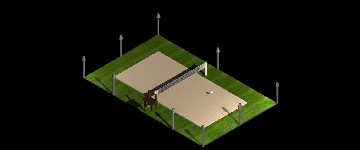
The reason that I decided to draw a volleyball court is because it is one sport that I have played since I was 12 years old. After playing a sport for 10 years, you really learn all of the ins and outs of the game. I have loved the game since I started in 7th grade and I have played ever since. I think the most exciting experience was playing in college. It was a completely different skill level and there was a lot more to learn than high school. I hope to continue my volleyball career competitively after college. Drawing this project was really fun and I enjoyed drawing it because I love the sport.
I first started with the grass surrounding the beach court. This was my bottom level so I needed to construct that first. After the grass was completed, I moved on to the beach court and got the right color for the sand. Surrounding the court on the edges of the grass are light poles. I thought that adding light poles would add a cool effect to the court because a lot of beach volleyball is played during the evenings, after work. I think if more courts had lights out they would be able to play longer into the night. The next thing I did was set up the poles for the net, and then added the net. This was a little difficult to do because I had to find the right color for the net to make it look like an actual net. I also added a referee’s stand because that is essential when playing a volleyball game.
I thought that hardest thing about this project was trying to get everything on different levels and making sure that the colors were different and not matching other levels. I also added lighting to the court and this was really hard to do. Getting the lighting just right was difficult and it took a lot of trial and error. Besides that, making sure everything was the right distance away and that everything was rendered correctly was difficult to do as well.
Michael
Hajec (Civil Engr. Technology)
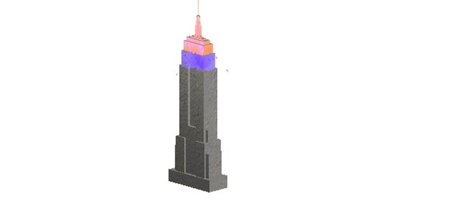
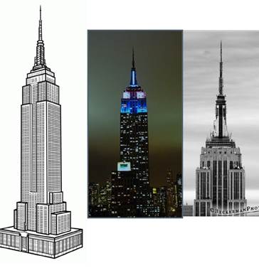
Rendered
Model-Left; Actual Photos-Right
For the final project, I wanted to do something that was related to structural engineering because that is my emphasis as a civil engineering tech. I looked up many different famous buildings and bridges and decided to go with the Empire State Building for many reasons. The first being that I wanted to choose a building with a blocky design because based on my current knowledge of Microstation, drawing in 3D with irregular shapes would have been extremely difficult if not unattainable at this stage of my learning. Another reason I chose to draw this is that it is the most identifiable building in all of New York State. The final reason is that since most buildings have flood lights that light up the skyline at night, I was able to incorporate lighting into the drawing.
I composed this drawing using numerous amounts of solid slabs and placing them on top of one another in a fashion similar to stacking LEGOs. Prior to starting, I found out the basic height dimensions of the building and scaled it down myself using a ruler. By doing so, the building is based on the scale that 1” equals roughly 187.6’. Not only is the building visually similar to the actual one but it is also a scaled down replica.
One of the biggest complications I ran into was that I was unable to find any architectural dimensions of the building. After searching for the dimensions I realized that they just wouldn’t make architectural drawings available for a building as prominent as the Empire State Building, for fear of terrorism. I was still able to get the length and width of the base and from there I was able to visually determine the remaining lengths and widths since I already have the correct heights. The building may not be exactly scaled down but it is extremely close based on the limited data I was able to retrieve. Another complication I ran into was the construction of the antenna at the top and the placing of the floodlights. I decided to choose the colors blue and orange for the flood lights because I am a die-hard New York Mets fan and whenever they win a big game they light the Empire State Building in their recognition.